Story
The power (electronic) modules are the forefront of the 21st-century energy innovation that seek to solve or reduce environmental issues while creating a more wealthy and comfortable society to all. Some of these innovations are hybrid and electric vehicles, photovoltaic and wind power generation, smart grid and home applications.
In addition to these goals, the growth of the power module market is also remarkable. According to the market research firm, Market Research Future®, the power electronic market alone is projected to reach USD 22 Billion by 2019 and the global power electronics market is expected to grow at a CAGR of approximately 3% during the forecast period 2020-2023. [1].
The low switching frequency resulting in limited bandwidth, slow transient response, and most importantly, the size and weight of magnetic components (inductors and transformers), and capacitors remain large. Therefore, it is always desired to operate switches at very high frequencies. However, the higher switching frequency increases the average switching power dissipation and the effects of parasitic electromagnetic behaviour. Hence, a trade-off must be made between reduced size, weight, and cost of components vs reduced switching power dissipation and the effects of parasitics, which means inexpensive low switching frequency devices [2].
In order for the power electronic module to meet these requirements, in addition to next-generation Si and SiC semiconductor devices and manufacturing and packaging technologies, simulation tools are also needed.
Ansys software (Q3D Extractor, Simplorer, Icepak, Mechanical) provide accurate solution to design, analyse or optimise any kind of power module layout from an electromagnetic, a thermal and a mechanical point of view.
The following example demonstrates the strength of Ansys tools to analyse a half-bridge power module with an emphasis on parasitic parameters with circuit simulation and thermal modelling.
Extraction of Parasitic Circuit Parameters
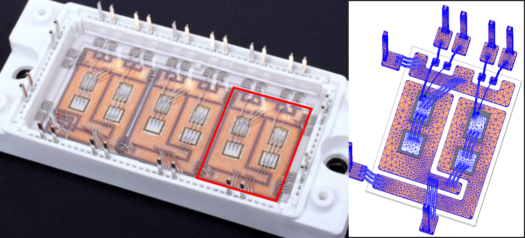
Ansys Q3D Extractor efficiently performs the 3D quasi-static electromagnetic field simulations, which required for the extraction of RLGC parasitic parameters from the conducting structure of the power module over a wide frequency range. It then automatically generates an equivalent SPICE circuit model [4].
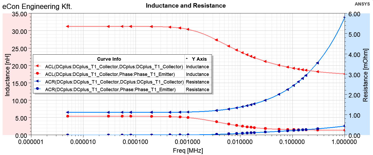
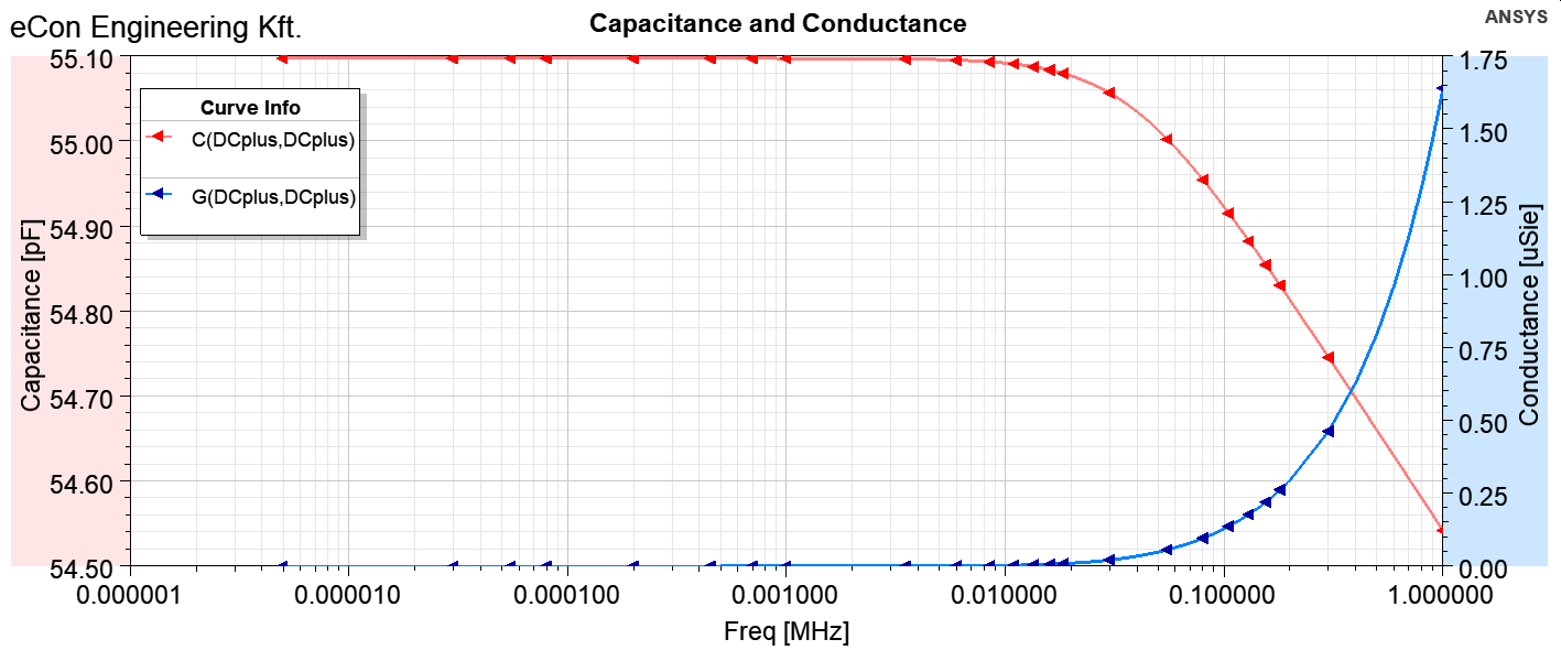
Fig. 2 shows an example of the frequency-dependent circuit parameters of the power module. The equivalent circuit model contains the self- and mutual term of inductance, resistance, capacitance and conductance. The RLGC model can be export in the most well-known file formats, like PSpice, HSpice, IBIS, Spectre or even m-file to Matlab. Besides, you can use Network Data Explorer to create a frequency-dependent S-parameter model for the module.
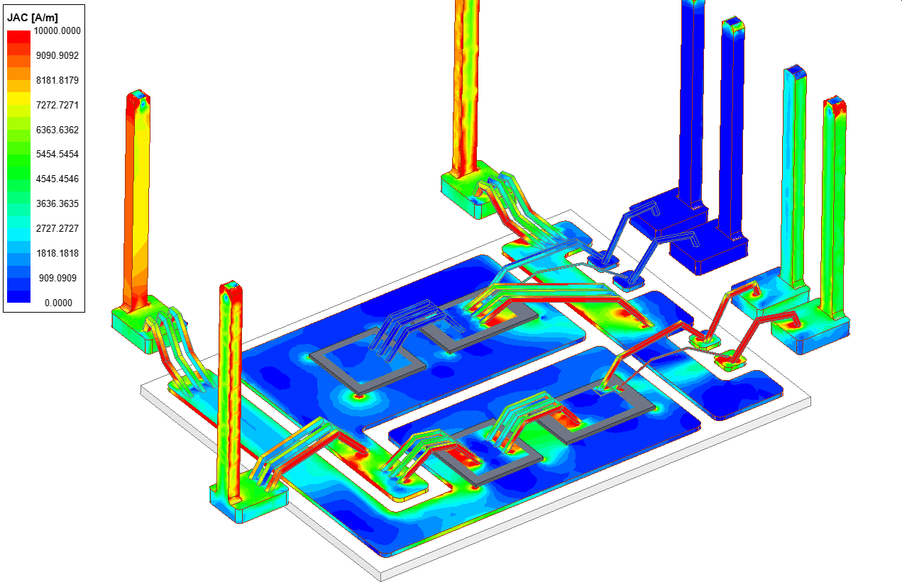
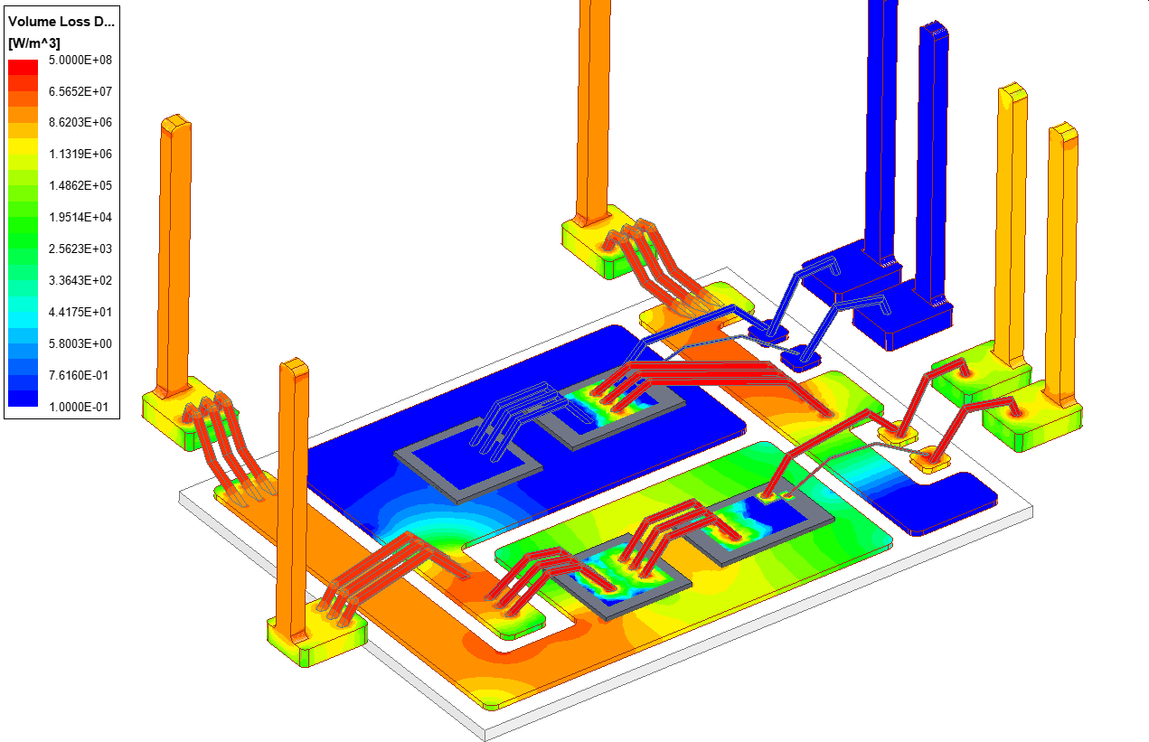
In addition to the circuit model, the current and charge distribution can also be determined with 3D field simulation. Thanks to the current distribution, the spatial distribution of losses can be determined, which can be used well in thermal simulation. Fig. 3 and Fig. 4 shows the surface current density distribution and the volume loss density distribution in the power module, respectively.
Circuit Simulation with Parasitic Elements
Fig 5. shows the circuit simulation of the power module in Simplorer. The simulation contains the three-phase power supply, the three-phase diode rectifier, the half-bridge inverter with gate drive and their state machine control and with the circuit model of the power module.
Ansys Simplorer is a multiphysics (electric, mechanical, hydraulic, thermal) circuit simulator, able to insert in a single schematic component and mix them with the mathematical operation described in terms of state space, block diagram, state machines and scripting algorithm. Simplorer offers the ideal environment for coupling control drives and FEM model of electromagnetic devices, but also the possibility to include ROMs (Reduced Order Models) from most of the different Ansys products (e.g. Mechanical, Fluent).
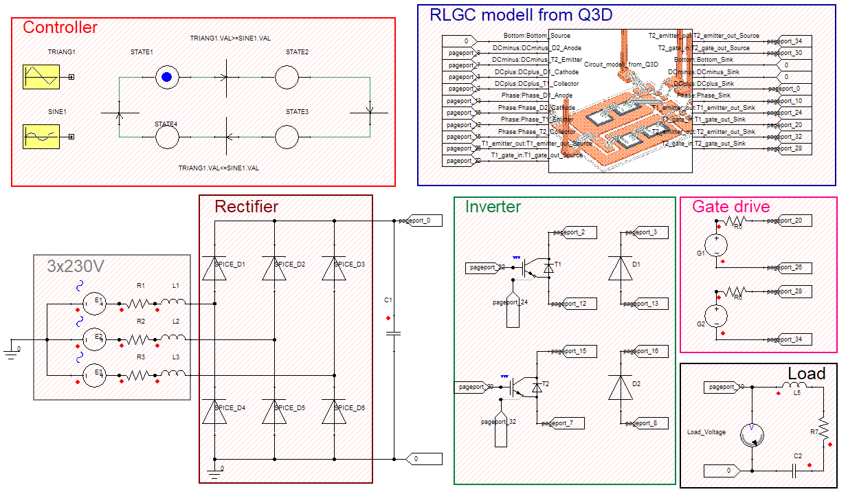
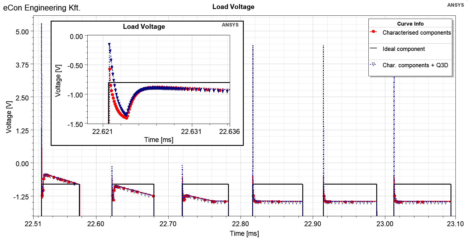
Fig. 6 shows the waveform of the inverter output voltage in three different cases. The “ideal component” means system-level semiconductors for quick evaluation of circuit behaviour and control algorithms. However, as the design evolves, developers need a more detailed version of these IGBTs, MOSFETs and diodes. Simplorer’s device characterization tool enables users to incorporate device information to accurately characterize the semiconductor devices for simulation. The difference between the result obtained with ideal and characterized semiconductors is clearly shown in Fig. 6. In addition to characterized semiconductors, Q3D can be used to take into account for the parasitic effects of module connections in the circuit simulation. The addition of the parasite circuit model from Q3D results in much larger overshoots. Thus, for example, to investigate voltage overshoots, which is one of the main sources of damages in the insulation of the electrical machine, it is essential to take into account of parasitic circuit elements.
Thermal Analysis of Power Module
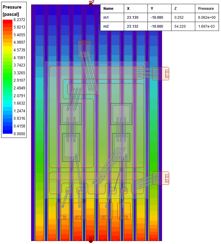
Calculating the pressure drop is one of the most basic and important aspects of any thermal analysis. Knowing the pressure drop in a cooling system is key because the fan must be able to deliver suitable pressure (in order to force the cooling air through the cooling system) and should provide required airflow performance within its operating range [5]. The pressure between pins of the heat sink in Ansys Icepak can be seen in Fig. 7. The temperature distribution in the power module on the heat sink for this forced air cooling is shown in Fig. 8.
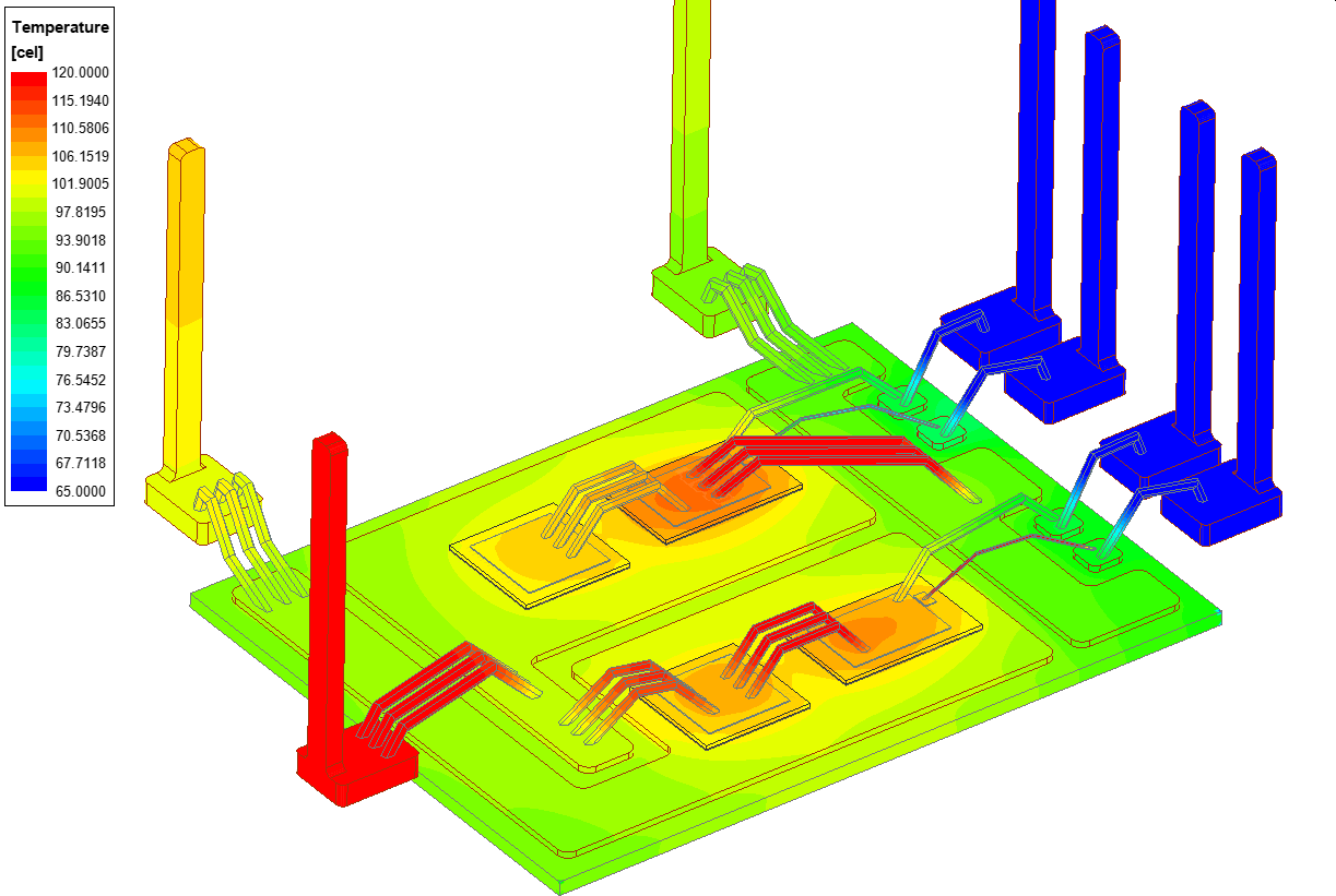
Ansys Icepak provides powerful electronic cooling solutions for thermal and fluid flow analyses of integrated circuits (ICs), packages, printed circuit boards (PCBs) and electronic assemblies. The Ansys Icepak CFD solver uses the Ansys Electronics Desktop (AEDT) graphical user interface (GUI). Electrical and mechanical engineers working in this environment will enjoy a completely automated design flow with seamless one- or two-way coupling from Q3D Extractor (Maxwell, HFSS also) into Icepak for steady-state or transient thermal analysis [6].
Conclusion
The used example shows well that Ansys Q3D, Simplorer and Icepak triplets are suitable toolchains for design and analysis of power module and its cooling system. The use of Ansys Mechanical software also helps to answers mechanical questions that arise during the manufacturing process of the module.
The result obtained with the Simplorer simulation shows well that it is important to take into account the parasitic phenomena of the power electronic module in addition to the characterized semiconductors.
References
- https://www.marketresearchfuture.com/reports/power-electronics-market-1069
- H. Rashid: Power Electronics Handbook – Devices, Circuits, and Applications, 3rd edition, Elsevier, 2011.
- https://www.wolfspeed.com/power/products/sic-power-modules
- Ansys Q3D Extractor – https://www.ansys.com/products/electronics/ansys-q3d-extractor
- Blinov, D. Vinnikov, T. Lehtla: “Cooling Methods for High-Power Electronic Systems”, Electrical, Control and Communication Engineering, Vol. 29, No. 1, pp. 79-86, 2011.
- Ansys Icepak – https://www.ansys.com/products/electronics/ansys-icepak
We are proud of our software support engineer, Dániel Marcsa, who wrote this article, it was also published in Elektrotechnika magazine.